
A few weeks ago a sensor lied to me for eight hours straight. The linear potentiometer that will measure suspension travel on our student race car sat perfectly still on my desk — while its output jumped around like a seismograph during an earthquake. Not drifting. Not offset. Just fuzz, edge to edge, all day.
I swapped jumper wires. I moved pins. I bought a replacement ADC because the one in my hand was clearly defective. The actual fix was one wire — a wire that had never existed in my setup. This is a story about a common ground problem, and about why the cheapest mistakes are the ones hiding under the word “basic.”
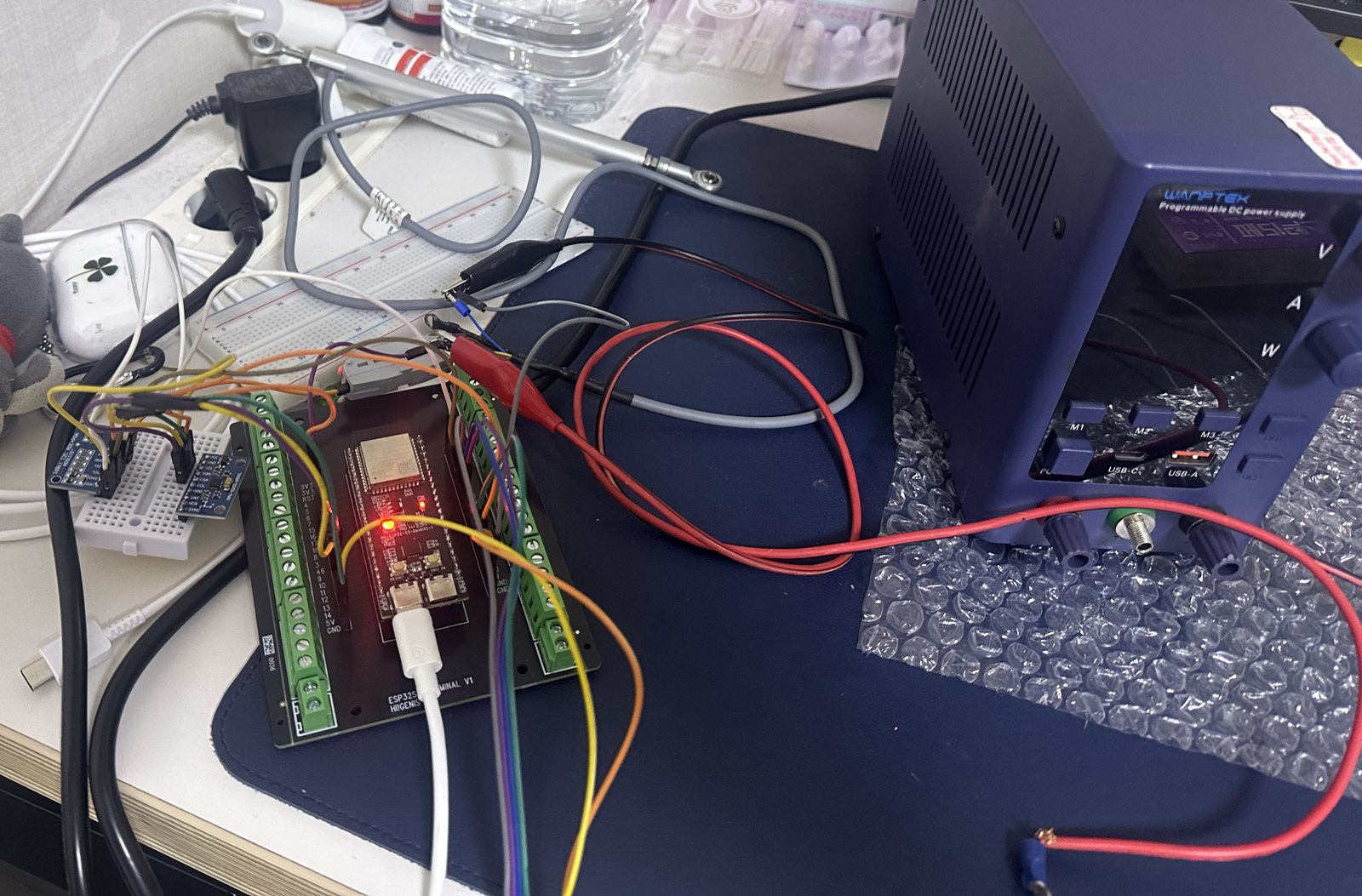
The project: this season’s datalogger rebuild for our student EV race car. An ESP32 reads an accelerometer and that linear potentiometer through an ADS1115, a 16-bit ADC, and writes everything to an SD card. On my bench the ESP32 ran off USB, while the sensor modules got their power from a lab supply — because a teammate had told me the dev board’s 5V pin was for power going in, not out. Hold on to that detail. It’s the entire story.
Four Hours in the Club Room, Four More at My Desk
The first bug of the day was almost funny: the firmware I’d written expected two ADS1115 modules, and I was holding exactly one. Past me had planned a bigger sensor suite than present me had wired. A quick recode, moving on.
Then the SD card refused to mount. The card was fine. The wiring matched every diagram I checked. Eventually, out of options, I ignored what I’d been told about the 5V pin and fed the SD module straight from the board itself — and it mounted instantly. I wrote it off as one of those things, filed it under “weird module,” and moved on. That was the answer, by the way. It introduced itself four hours early, and I didn’t recognize it.
Next: the ADS1115. With the potentiometer connected and completely still, the readings shivered — a jittery band of static where a flat line should have been.
So I did what any calm, rational engineer does. I reseated every jumper. Replaced them. Moved the module to different pins. Ordered a fresh ADS1115, because obviously the chip was bad. Four hours of this in the club room, and nothing moved the needle — or rather, everything kept moving the needle, which was the problem. I packed the whole breadboard mess into my bag, went home, and spent four more hours running the same experiments at my desk, but angrier.
Somewhere past hour eight I ran out of parts to blame. So I stopped staring at components and looked at the bench as a system: ESP32 on USB power. Sensors on the lab supply. Two power sources — and not a single wire connecting their grounds. The SD module that had “fixed itself” on the ESP32’s pin fit the same pattern: everything powered by the board worked, everything powered by the supply misbehaved. This wasn’t three separate bugs. It was one bug wearing three costumes.
I moved the ADS1115’s 3.3V and ground over to the ESP32’s own pins and watched the trace flatten into a clean line. Swept the pot through its travel: a smooth ramp from 3.3 volts down to zero, no fuzz. Logged the accelerometer and the potentiometer to the SD card, verified the files, and closed the laptop like a man leaving a casino at dawn — technically a winner, mostly just tired.

If you want to see the rig itself — the ESP32, the potentiometer, the SD module that started all of this, and the viewer with a logged run — here’s a quick walkthrough:
What a Common Ground Problem Actually Is
A voltage is not an absolute number that lives inside a wire. It’s a difference between two points. When an ADC reports 2.1 volts, it means “2.1 volts above my ground.” That sentence only works if the ADC and the sensor agree on where zero is.
Power the sensor side from one supply and the logic side from another, with no ground connection between them, and each side’s zero floats relative to the other — picking up whatever offsets and hash the two supplies feel like producing. Your signal wire is then measured against a reference that keeps moving. That’s not a bad chip. That’s physics doing exactly what you asked, which is worse. Digital lines fail the same way: HIGH and LOW are just voltages relative to ground, so without a shared reference the ESP32 and the SD module can’t even agree on what a 1 is. Mount failures, corrupt data, ghosts. That’s the common ground problem: everyone talking, nobody agreeing on zero.
The rule fits in one sentence: every device that exchanges a signal must share a ground reference. If you power a module from an external supply, run a wire from that supply’s negative terminal to your controller’s GND. That’s it. That’s the eight-hour wire. And to be fair to my teammate — on many dev boards the 5V pin really is a power input. But when the board runs off USB, that same pin carries the USB rail and can feed a small module, ground included, which is exactly why everything I moved onto the board started behaving. The bad advice wasn’t the pin. It was splitting power without joining grounds.
Bad Grounds in Your Car: Same Physics, More Rust
Your car is one giant shared-ground system. The battery’s negative terminal bolts to the body, and the chassis itself is the return path for almost every circuit in the vehicle. Every sensor, every light, every module measures and switches against that chassis reference — millions of cars, one big common ground.
So when one ground connection corrodes or works loose, the symptoms scatter in ways that look unrelated: gauges that wander, headlights that dim at idle, a sensor that throws random codes, relays that click for no reason. Classic bad-ground trouble rarely announces itself as a ground issue — it masquerades as five different broken parts. One bug, several costumes. Sound familiar?
I haven’t chased a corroded ground strap on a road car myself — my lab was a breadboard — but a car’s bad ground is the street version of my common ground problem, and the diagnostic carries over directly: measure, don’t guess. With the circuit switched on and under load, put a multimeter between the battery’s negative post and the component’s ground point. You’re reading the voltage lost across the ground path, and a healthy connection drops close to nothing — tenths of a volt at most. Noticeably more, and you’ve found resistance where none should be: clean the contact, tighten the bolt, or replace the strap. If you’re new to this kind of measurement, I’ve written up the multimeter routine I use, and the $35 meter that survived our race season is more than enough for the job.
On the actual race car, none of this will depend on my memory. Everything runs off one custom PCB — one board, one ground plane, every component sharing the same reference by construction. That’s the grown-up version of the fix: design the mistake out instead of remembering not to make it.
The lesson from that night is the one I keep relearning: fundamentals matter. I’ve already killed a motor controller with one reversed connector, and now I’ve lost a full working day to one missing ground wire. The basics aren’t the beginner material you graduate out of. They’re the material that waits, patiently, for hour eight.